Značajke


Na ovoj stranici koriste se kolačići. Više informacija potražite u Politici kolačića.
Ova stranica koristi kolačiće kako bi se osiguralo bolje korisničko iskustvo i funkcionalnost stranica. Više informacija o kolačićima možete potražiti ovdje, a za nastavak pregleda i korištenja stranica, kliknite na "Prihvaćam sve" ili "Uredi kolačiće"
Ova stranica koristi kolačiće. Više informacija potražite na Politici kolačića.
Odaberite koje vrste kolačića želite prihvatiti::
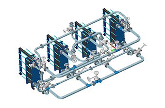
With this newly added module, it is more convenient than ever to design pipes with flexible routing ways, a vivid display of flow direction, rigorous specifications, powerful editing functions, etc. (not available in some countries/regions)
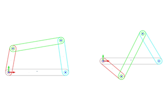
Turn objects into sketch blocks and create new objects by inserting blocks and quickly changing their sizes.
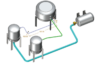
Objects in a 3D sketch are three-dimensional, can be captured or constrained, and support the use of Intelligent Point Reference. You can directly use 3D sketches as contours, paths, curves, etc. for modeling.
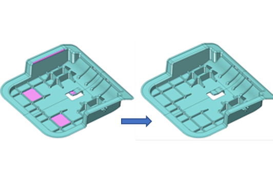
Analyze and quickly repair abnormal conditions (e.g. open edges, gaps, duplicate faces, intersection loops) found in the geometry of imported files.
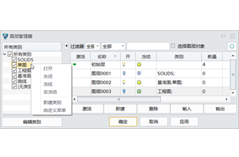
Quickly sort and organize model features in 3D: easily arrange layers via the Category attribute; control and edit layers with the Filter and Select Object in Layer functions.
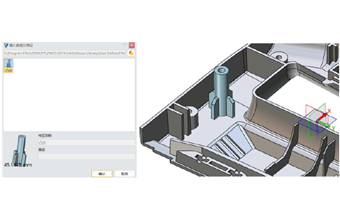
Create one feature with all features of some geometries so that you can easily reuse features and avoid repetitive work.
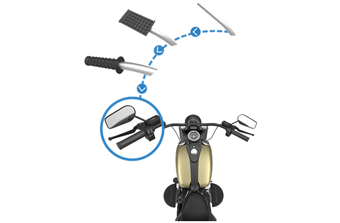
Raster images can be embossed on the surface of your model nice and quick with the Emboss command. Morph and Winding can be used for objects, surfaces, and STL models.
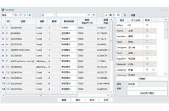
The attribute information of all parts can be displayed in rows and columns of a 3D BOM, edited, and directly exported to 2D engineering drawings.
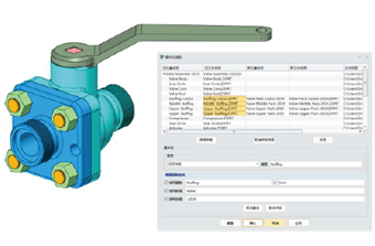
You can modify part names in batches with Rename Assembly without changing the assembly structure to rapidly morph serialized assembly items.
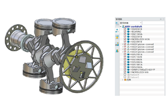
By changing the degrees of freedom of the sub-assembly in the general assembly, you can continue changing the sub-assembly components with DOF in the general assembly.
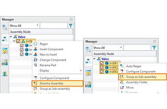
You can disassemble and drag the sub-assembly components, turn components into a sub-assembly, or save the sub-assembly as a new file or new object.
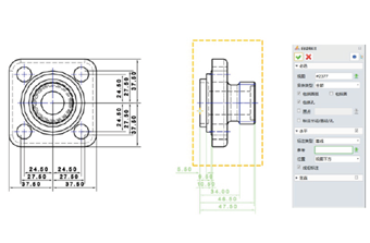
Efficiently generate linear/diameter/radius/hole dimensions and so on with all the objects in a view or annotate the selected objects.
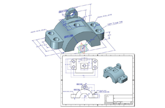
You can add annotations to the 3D model. All the PMI objects can be listed in the view manager and directly exported to 2D engineering drawings.
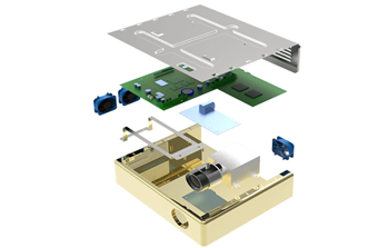
Complex sheet metal design can be completed with Bend, Loft, Louver, Punch, etc. The imported files can be converted into sheet metal parts for unfolding, bending, or design. The advanced FastBlank functions allow you to generate the unfolded effect.
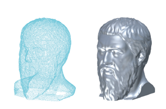
Prepare point cloud data for surface generation by deleting, trimming, dividing, simplifying the imported point cloud. A perfect mesh can be created from the processed point cloud and automatically converted into a NURBS surface.
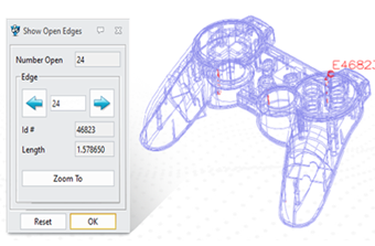
Accurately analyze and repair various geometric topological issues, including cracks, open edges, etc. Efficiently process model gaps and reconstruct missing faces to ensure a complete model and data quality.
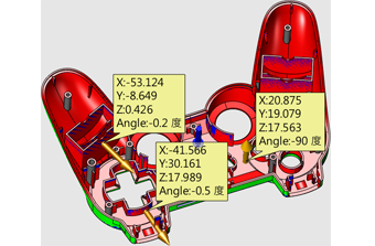
You can check and verify the manufacturability of product structures with tools such as Draft Analysis, Thickness Analysis, and Undercut Analysis. Also, intuitive analysis.
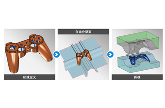
The core, cavity, and other areas can be defined through parting lines or parting faces. Various handy tools are available for holes and parting faces creation, making it simple and clear to transform from the product to core and cavity.
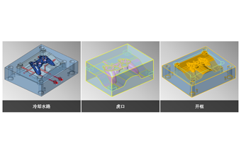
Specialized tools are provided to quickly create runners, cooling systems, slide and groove, which can also be easily and intuitively modified.
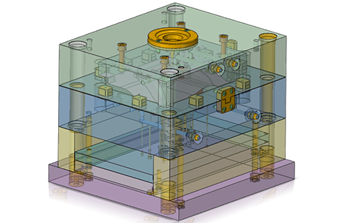
The built-in library of mainstream mold bases and standard parts (MISUMI/FUTABA/HASCO/DME/LKM, etc.) are provided and user can create and customize their own standard part library.
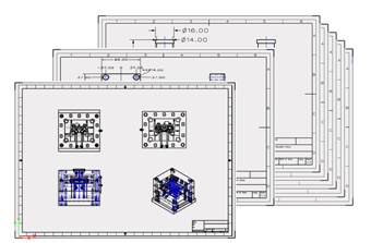
Mold attributes can be automatically recognized. The engineering drawings of all components can be generated effortlessly according to the predefined type template while dimensions can be automatically added according to custom settings.
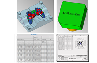
There are multiple ways to create electrodes. Functions such as bills of electrodes, electrode engraving, automatically generating electrode drawings, etc. can facilitate your electrode design.
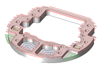
Features such as holes, grooves, and steps in parts can be automatically recognized so that efficient drilling programs and milling toolpaths can be generated according to user needs, greatly reducing your programming time.
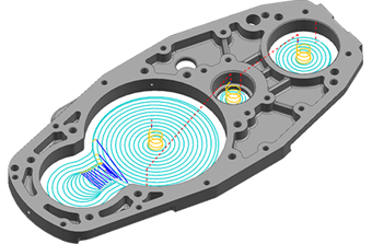
Volumill™ for ZW3D can help generate optimized toolpaths with 50%-80% machining cycle time saved. Plus, the full depth of cutters can be used, sparing costs of cutting tools up to 75%.
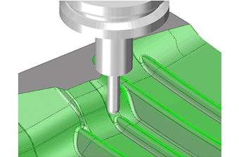
Over 40 types of 3X machining operations are available so that you can deal with all kinds of manufacturing work at ease. With QuickMilling, smooth toolpaths can be easily generated to guarantee high-quality surfaces.
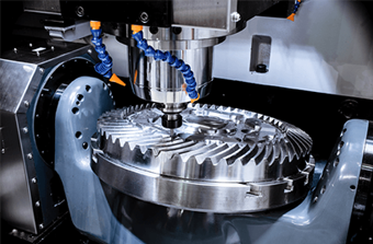
A complete solution for indexing and 4 to 5-axis machining that can work with STL files is available. You can make efficient use of functions like Swarf, Drive Curve, Flow Cut, etc. to produce fine components.
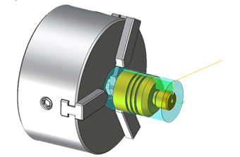
Inside and outside Roughing, Finishing, Grooving, Threading, Facing, and Drilling are easy to use and useful for handling most turned parts. Turning cycles, simulation, and verification expedite the switch from manual programming and machining safely.
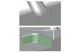
Get better toolpaths, improve machining efficiency, and avoid tedious parameter adjustments and toolpath re-calculation. The entire or partial toolpaths can be edited flexibly with tools like Trim, Re-order, Re-link, Extend and Transform.
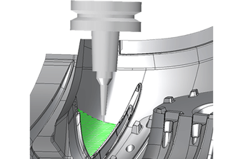
Wireframe Simulation, Solid Verify, and Full Machine Simulation can realize reliable, efficient, and safe machining by detecting collisions, analyzing residue, etc. to avoid damaged machines, poor quality, and delayed delivery.
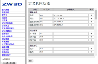
ZW3D comes with more than 80 default post-processors that work with all kinds of CNC milling and turning machines. Professional and localized post-processing support is at your service.

